[2006 ISMAR Paper]
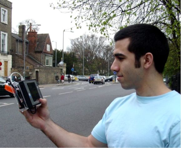
Handheld devices equipped with a video cameras provide an excellent platform for mobile visualisation in outdoor environments (see Fig.1, left). The use of augmented reality enables the display of 3-dimensional information over a view of the real world (see Fig.1, right). However, to correctly overlay such information, the position and direction of the video camera within the environment needs to be known very accurately. To make this possibe, we developed a tracking system that combines input from video images, electronic sensors measuring rate of rotation, gravity and the Earth's magnetic field and GPS.
 Fig.1: (Left) A user operating a hand-held augmented reality unit tracked in an urban environment. (Middle) Live shot showing the unit tracking a building. (Right) Screenshot from a pose close to the left images with overlaid building outline.
Click any image for larger resolution.
Operation
The overall tracking framework consists of an edge-based tracking system, that uses a coarse, but textured 3D model of an urban environment. A realistic view from the last camera pose is created, from which edgels are extracted using a standard edge detector. These edgels are then projected back onto the model to obtain the 3D coordinates of the sample points. The edge search is conducted using an appearance-based model of the edge instead of a simple edge detector. See Fig.2 for an example of the individual steps involved.
 |  |  |  |  |
| (a) Rendered 3D model | (b) Edgel extraction | (c) Prior pose | (d) Edge measurements | (e) Updated pose |
Initialisation
To enable the system to start at any location within a city, we enhanced it with a GPS sensor which provides the absolute location relative to the Earth. However, GPS localisation has large errors (5-10m) in urban environments due to occlusion of satellites in narrow streets and reflections of the signals on buildings. The camera-based tracking system described above cannot start from such a coarse estimate of position. Therefore, a search pattern is employed to quickly check a number of positions around the GPS estimate. Various heuristics are used to speed up the search process.

Fig.3: Overlay of the sample positions used in the search, covering the uncertainty in the GPS position shown as an ellipse. The yellow part denotes street and sidewalks where a user could be.
Robustness
Outdoor environments are often less controlled than indoor situations and disturbances such as cars and buses driving past or people walking through the view of the camera break the assumptions of the edge-based tracker. It can easily lock onto edges of such transient occluders and fail quickly. Therefore, an additional recovery mechanism is required to improve the overall robustness of the system.
The system uses a statistical test to decide if the edge-based tracking failed. If so, it compares the current video frame against a set of frames it saw during the last minute. The difference to the frame locking most similar to the current video frame is the used to calculate a new camera pose. This pose is then used as the prior for another iteration of edge-tracking to allow the tracker to lock on again.
Model
Two sites were modelled to provide test environments for evaluations of the system's performance. The first site is Trumpington street in the City of Cambridge. The model of a front of buildings was created by Duncan Robertson using the Photobuilder software and kindly made available for experiments. The second site is the main court of St. Catharine's College, modelled using a commercial software package. Both models were registered with vector map data obtained from the Ordnance Survey agency to provide ground truth for accuracy evaluations. Fig.4 shows overhead and frontal views of the two models with registered map data shown as blue lines.
 |  |
 |  |
Handheld AR platform
The tracking system is implemented on a hand-held computing platform. The platform consists of a VAIO U-71 tablet PC with 1.1 GHz Pentium III M CPU. A USB 2.0 camera with a 3.6mm lense and an Xsens MTx sensor are mounted rigidly to the back of the device. Here are some images of the setup:


Fig.5: (Left) Frontal view showing the typical mode of operation. (Right) A camera (circuit board and black lense) and inertial sensor pack (orange cube) are mounted to the back of the device.
Results
Fig. 6 shows the plot of a 2min walk through the main court of St. Catherine's College. After walking along the grass centre, the camera rotates in various directions to evaluate the performance under close proximity to modelled structures. In these situations tracking fails at several points due to larger discrepancies between the flat textured model and the actual building. However, automatic recovery is possible through the frame store. These recoveries are evident as sudden large jumps in position, as the reference position from an earlier frame is used. The pose estimate quickly converges back to the true position. Closer to the end of the sequence, the recovery cannot obtain a good position anymore and the tracking fails.

Fig.6: Overhead, front and side plots of camera centre location from a sequence of walking through St. Catherine's College main court. The walk starts in the lower right corner, along the grass centre and finishes with a set of pans in the upper left corner. Tracking fails during the last rotations leading to wrong pose estimates. Individual large deviations are due to incorrect position estimates from a reference frame, but converge quickly to the right location again.
The video below shows the system in operation. Due to the combinations of inertial sensors and the recovery mechanism it is quite robust and avoids common failure modes such as fast motion, total occlusion, or misalignments of the edge-based tracker. While its absolute localisation performance as described by the variance and errors in absolute pose is not perfect, the quality of overlays is not affected, because the errors in image space are minimised, which is most important for convincing augmented reality applications. Visible errors in the graphics overlays are mostly due to the vertex-based radial distortion compensation.
Publications
- Gerhard Reitmayr and Tom Drummond
Going Out: Robust Model-based Tracking for Outdoor Augmented Reality
Proc. IEEE ISMAR'06, 2006, Santa Barbara, California, USA. [BIBTEX]
Presentation - Gerhard Reitmayr and Tom Drummond
Initialisation for Visual Tracking in Urban Environments
Proc. IEEE ISMAR'07, 2007, Nara, Japan. [BIBTEX]
Presentation
Media
- A short video (DivX) demonstrates tracking of a hand-held augmented reality system in urban environments.
- A short video (XVid) showing a full search to initalise the system.
- A video (XVid) comparing the performance of the correcting GPS with the predicted error (red) vs. the raw GPS measurements (blue).
No comments:
Post a Comment
Note: only a member of this blog may post a comment.